How to Choose the Best Camera for Barcode Scanning
Abstract
Viziotix’s barcode scanning SDK is versatile and powerful enough to integrate with any type of camera. However, camera specifications significantly impact overall system performance. The optimal camera choice is the one best suited to the specific requirements of the application. This document explains how to choose the best camera for barcode scanning by discussing the key parameters for selecting a camera for barcode scanning. It discusses its sensor, an optical lens, and other acquisition elements for a defined system solution. It includes calculation formulas for sensor and optics specifications, as well as a practical example with sensor recommendations.
Key Takeaways
- Whenever possible, Viziotix recommends the use of a monochrome sensor for barcode scanning applications
- Color sensors reduce the effective resolution, are less efficient in low light and they run algorithms that generate image artifacts that can decrease barcode decoding performance.
- Any embedded image processing or compression should be deactivated.
- We recommend that you calculate sensor resolutions based on needing 1.5 pixels per bar or 2 pixels per element. But note that Viziotix’s decoder can read 1D barcodes down to 0.7 pixels per narrow bar, thanks to the advanced Nano-Scan algorithm.
- Whenever possible, consider adapting the type of barcode and the size of your labels to greatly reduce camera and system constraints.
- Use the formulas given to calculate sensor size and objective lens requirements.
- Ensure that you take into account any motion and follow the guidelines on shutter types and illumination.
Table of Contents
Introduction
Viziotix specializes in barcode scanning for automation and mobile solutions used in logistics, transport, retail, healthcare etc., including camera-equipped Robots and Drones, or fixed systems such as automated storage, conveyor systems, sorting systems and medical analysis machines.
The barcode scanning challenges of these systems include:
- Varying distances between camera and barcodes;
- Size of the barcodes;
- Number of barcodes in the image (see Maxi-Scan);
- Movement;
- Illumination levels;
- Requirement for high-volume, high-speed processing.
The question of how to choose the best camera for barcode scanning solutions requires that you examine the overall requirements and the ambient conditions. There is no single camera suitable for every barcode scanning solution. Normally, a system designer needs to understand the minimum requirements in order to specify a cost-effective camera. Below we look at the key considerations and workings necessary to make these decisions.
Choosing Cameras and Sensors
Although cameras consist of more than just a sensor, for our purposes, we will concentrate on camera sensor types.
Color vs Monochrome Cameras for Barcode Scanning
Cameras with color sensors are the most common type found because they are extensively used in smartphone cameras. For that reason, their prices are usually lower than monochrome but their performance in barcode scanning is significantly lower. So whenever possible, Viziotix recommends the use of a monochrome sensor for barcode scanning applications.
In this section, we provide more details on comparing color and monochrome but overall, as far as scanning performance is concerned, color sensors provide less than half the performance of monochrome sensors for the same resolution. Firstly, let’s review these two sensor types:
Monochrome sensors: a monochrome sensor transforms photons into electrical charges by photoelectric effect then into a digital signal after conversion of the charges into voltage, amplification and digitization. As no optical filter is needed in front of the photoreceptors of the sensor, this type of sensor has a good sensitivity with good performance in low-light conditions.
Color sensors: a color sensor is a monochrome sensor on which an optical color filter has been applied. The sensor pixels are grouped by 4: one pixel with a red filter, one pixel with a blue filter and the other two pixels with a green filter. This color filter pattern is named “Bayer pattern”.

Since each pixel of the sensor has only partial color information (R, G or B), the other color components must be interpolated from neighboring pixels. This interpolation generates a loss of resolution that, for barcode reading, can be estimated at 1.5 on each axis (X and Y).
At the same time, color filters reduce the sensitivity of the sensor since each photoreceptor receives only about a third of the visible light. Because of this reduced sensitivity, and the need to interpolate missing color components, most of the color sensors run embedded image processing algorithms that:
- Filter noise while increasing image sharpness
- Interpolate missing color components
These algorithms generate image artifacts that can decrease barcode decoding performance
Bayer to Color Conversion on Color Sensors
As above, color sensors are based on a Bayer filter pattern applied on a monochrome sensor. Interpolation of missing color components is needed. This step is named demosaicing. A lot of algorithms can be used for this. Here are some of them, included in OpenCV (images are zoomed):
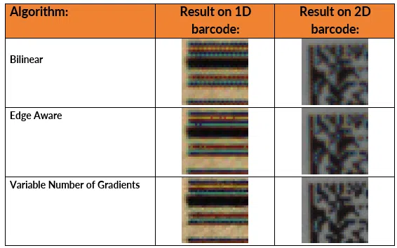
As it can be seen in these images, demosaicing algorithms generate artifacts that might look ok to the eye, but they reduce decoding performance.
If a color sensor must be used, the Viziotix SDK includes a specific Bayer-to-monochrome conversion to virtually remove the Bayer filter. Even though this filter was specifically designed for barcode reading, better decoding performance will still be achieved with monochrome images (see results below).

Noise filtering and sharpening
As mentioned earlier, due to the Bayer filter, the sensitivity of the sensor is decreased, and this increases the noise. Demosaicing also creates noise in the form of artifacts. Therefore, since color sensors are designed for human vision, most of them contain algorithms that reduce image noise and at the same time increase image sharpness to obtain more « pleasant » images for human eyes.
Here is an example of a color image that shows the result of this processing (the image is zoomed):
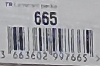
The edges in the images are analyzed and depending on their contrast, they are considered as noise and are blurred, or as real edges and are sharpened. This leads to strange effects when the resolution of the elements to be analyzed (barcode or text) is close to the resolution of the sensor.
In the case of barcodes, the size of the bars/spaces can become inconsistent, the bars can be merged by noise filtering or split by edge sharpening, sometimes making them undecodable.
Even though the Viziotix SDK contains algorithms to deal with these types of images (Nano-Scan for example), embedded image processing in color cameras (sometimes also in monochrome cameras) should be deactivated. JPEG compression for transmission should also not be used as it also generates artifacts around edges.
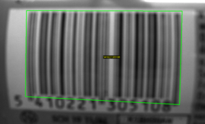
Image and Sensor Resolution
The sensor resolution, usually denoted in MP units for megapixels, is the number of pixels in the sensor matrix. The choice of the sensor resolution depends on the surface of the scene to be captured, the size of the barcode (X-Dimension) and the reading capabilities of the decoder software.
Viziotix’s decoder can read 1D barcodes down to 0.7 pixels per narrow bar, thanks to the advanced Nano-Scan algorithm. However, we recommend a minimum of 1.5 pixels per narrow bar of a 1D barcode (e.g. UPC barcode) and 2 pixels per module for a 2D code (e.g. Data Matrix) to provide some margin and obtain optimal scanning performances in every environment.
Based on this recommendation, the minimal required sensor resolution is evaluated as the product of minimal width W and height H of sensor image using the following equations:
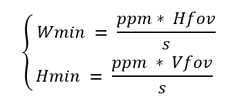
where ppm is the minimum pixels per element given by the decoder capability, s the size of the smallest bar or module of the code, Hfov and Vfov the horizontal and vertical field of view (i.e. the size of the scene to the captured).
As an example, for a scene size of 1.2 m x 0.8 m, a UPC barcode with bar size 0.33 mm and 1.5 pixel per bar, we get a minimal sensor resolution of Wmin x Hmin = 5452 x 3634 ≈ 20 MP (for a monochrome sensor).
It is important to notice here that the size of the barcode is a major limiting factor. Indeed, the same scene but using a data matrix code of 1 mm module size would only require a sensor resolution of about 4 MP.
So, whenever possible, consider adapting the type of barcode and the size of your labels to greatly reduce constraints on the camera resolution
Illumination and Sensor Shutters
Depending on the ambient light level and acquisition conditions, it may be required to add lighting to the scene. This is especially true when the barcodes to scan are moving. Fast motion requires short exposure times to avoid blur in the image. The shorter the exposure time, the shorter the time for the sensor to collect light, and the lower the contrast of the image will be (i.e. low Signal-To-Noise ratio (SNR)). A very low contrast or SNR dramatically reduces the decoder’s capacity to identify barcodes in the image. So, it may be necessary to add external illumination to the scene to compensate.
There are two possible lighting principles one can use: continuous or strobe illumination. The choice of technology depends on the amount of light required.
Continuous lighting is easier to handle, require less sophisticated electronic drivers but their usage is not adapted for high intensity demanding scenarios because they generate a lot of heat and consume a lot of power. Furthermore, high intensity lights are subject to restriction due to photobiological safety (see IEC 62471 standard).
Strobe illumination allows the light pulses to be synchronized with sensor exposure time, thus providing high intensity lighting only when it is really required. It is more complex to manage and needs more complex electronics but, especially in short exposure scenarios, it is the method of choice to provide high peaks of light over a short time intervals while keeping the overall mean intensity below the limits of photobiological safety standard (as shown below).
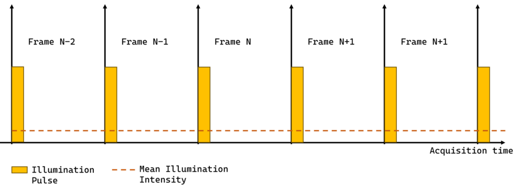
Whether or not the lighting system is strobed drives the choice of which sensor shutter type to use.
There are 3 types of sensor shutter: global shutter, rolling shutter and rolling shutter with global reset. At equivalent resolutions, rolling shutter sensors are the cheapest and global shutter sensors the most expensive. In this section we present what are the differences and why it matters.
Global Shutter
In a global shutter sensor, all rows of the sensor matrix are exposed simultaneously. After exposure, pixel values are transferred one row at a time during frame readout (see diagram below).

While exposure time can be reduced down to very small time intervals (e.g. 50 microseconds), frame readout time stays constant. Overall frame readout time is the product of individual row readout (typically about 5 to 10 microseconds) by the number of rows of the sensor. So, even with very short exposure times, the frame rate is limited by the readout time of the sensor. Synchronizing a strobed illumination with a global shutter is straightforward: all global shutter sensors provide an output signal (flash-out) to drive the illumination during exposure. So, whenever strobe illumination is required, global shutter sensors are the logical choice.
Rolling Shutter
In a rolling shutter sensor, rows of the sensor matrix are exposed and readout in sequence:
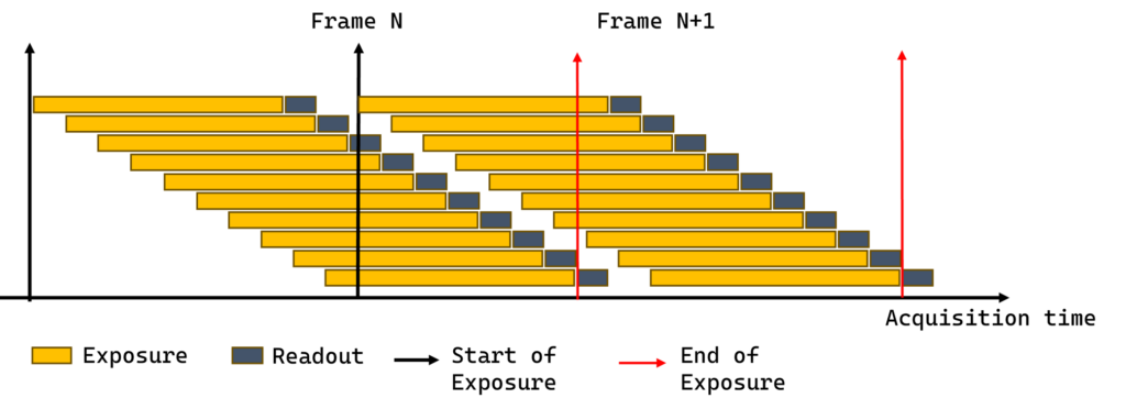
The pace of this sequence is driven by the readout time. Since sensor rows are not exposed at the same time, not all parts of the image of the scene are recorded at the same instant. This can introduce well-known image distortions under very high motion.
In typical scanning applications, this effect is not predominant enough to be a problem and whenever present, the Viziotix barcode scanning SDK can cope with some level of distortion of the barcodes. In general, rolling shutter sensors do not provide an output signal related to exposure time to drive illumination. In any case, the sequential nature of the exposure makes it very hard, if not impossible, to synchronize with pulsed light. Either pulses of light are so short that some lines are not illuminated during exposure, or the pulses are so long or so frequent that illumination becomes almost continuous.
Global Reset
Some rolling shutter sensors are compatible with a specific reset mode called Global Reset:

In this mode, a rolling shutter sensor tries to emulate global shutter behavior by starting the exposure of all rows at the same time. However, as in rolling shutter mode, the exposure of each row ends when the readout starts. Under constant lighting, lines at the bottom of the image receive much more light than lines at the top. In other words, the image is under exposed at the top and over exposed at the bottom, This makes global reset mode unsuitable under ambient light.
However, in a completely dark environment, the illumination can be pulsed during the exposure of the first line only, leaving other lines without any light during readout. This will ensure that all lines of sensor receive the same amount of light.
In summary, we provide the following table as a guideline to select an illumination and sensor type adapted to the application:
Environmental
Lighting Factors
|
Ambient light environment |
|
Full Dark room (0 lux) environment |
Static scene or slow motion
Constant illumination with Rolling Shutter |
| Constant illumination with Rolling shutter |
Higher Motion Scene (see below)
Strobed illumination with Global Shutter |
| Strobed illumination with Global shutter or Global Reset |
The threshold between slow motion and high motion depends on the size of the barcode but, as a rough estimation, this can be taken as about 5 to 10 cm/s for 1D barcodes and about 10 to 20 cm/s for 2D codes.
Optics and the Objective Lens
Once the sensor is selected, an objective lens adapted to the sensor characteristics and to the application constraints is required.
There are 3 important characteristics to take into account:
Sensor format:
The objective lens specification must take account of the size of the sensor. Using an objective lens designed for a smaller sensor will obscure parts of the incoming light and leave image borders underexposed creating vignetting effects
Optical resolution:
The optical quality of the objective lens must resolve the physical size of the pixel in order to use the sensor at its full capacity. Lens manufacturers provide the smallest pixel size that a lens can resolve, and this value must be lower than (or at least equal to) the pixel size of the selected sensor.
Focal lens:
The focal length is selected from the distance to capture. For a given length and width of a scene (i.e. horizontal FOV and vertical FOV), capturing at short distances means larger angles of capture which correspond to short focal lengths. On the contrary, capturing at longer distances requires a longer focal length. The following equation give the focal length f in function of the field of view FOV of the scene, the distance D of capture, the width of the sensor in pixels W and the physical size of the pixel s:

As an example, for a scene field of view of 1.2 m, a sensor width of 1980 pixels (Full HD resolution), a pixel size of 2.5 microns and a distance of capture of 2m, we get a focal length of 8.25 mm.
Since, in general, objective lenses are only available for some specific discrete values of focal length, you need to choose the closest available, an 8mm focal length lens in our example. From the exact focal length value, we can get the exact distance of capture using the previous equation.
Alternatively, we can also compute the angular FOV (θ_H,θ_V) from the following equations:

Additionally, capturing the scene at very short distances, or, in other words, under large angles (> 60 degrees) can cause barrel distortion in the image which reduces scanning performance. To avoid this, a first approximation is to make sure that the distance of capture is always larger than the field of view.
Barcode Scanning System Optimization
Now that we have the right sensor, right optics and right illumination for our scanning application, we need to optimize some parameters related to the depth of field and the acquisition to get the best overall performance.
Exposure time:
The exposure time must be carefully set to avoid blur in the image when barcodes are in motion. The idea is to make sure that during the exposure, the barcode has moved less than half the size of a narrow element (bar or module). Therefore, we can compute the maximal exposure time t from the width of narrow element δ and the speed of motion S with the following equation:

For instance, with a standard EAN barcode (width of narrow bar is usually 0.33 mm) moving at 20 cm/s, the maximal exposure time must be t < 0.82 ms. This illustrates that, even in relatively slow motion, capturing 1D barcodes without blur requires short exposure times.
Analog gain:
When working with short exposure times, image contrast may be low. To enhance barcode readability, increase the sensor’s analog gain to boost contrast; however, this also raises image noise, so the signal-to-noise ratio remains the same. In barcode scanning, a high-contrast image with noise is often preferable to a low-contrast or blurry one. Therefore, for optimal results, it’s best to use a fixed exposure and automatic analog gain
Depth of field:
The depth of field (or DOF) is the distance range for which the image is in focus. By extension, in scanning applications, the DOF is the distance range where a barcode can be decoded. A larger DOF gives flexibility on the capture distance which can be beneficial in some scanning applications where the camera to barcode distance is not fixed.
DOF depends solely on the optical aperture of the objective lens. Aperture is given in “F-number” units (or F#) which is the divider of focal length f. For instance, an aperture F#4 means a diameter of f/4, and more generally the smaller the F# the larger the aperture and the smaller the DOF is. Increasing depth of field requires smaller and smaller optical aperture (so larger F#) at the expense of the amount of light collected by the sensor (proportional to the square of F#). So, reducing aperture increases DOF but reduces image quality in return, to a point, where image quality becomes too degraded and/or the diffraction limit is reached.
In general, for scanning applications, the best trade-off between DOF and image quality is found with an aperture between F#4 and F#6.
Worked Example to Choose the Best Camera for Barcode Scanning

To conclude this guide, this example applies the above guidelines to a typical scanning scenario in logistics. The use-case consists of a fixed barcode reader mounted on a stand to scan barcodes on pallets passing in front of the scanner while they are moved by a forklift.
Let us assume that the barcodes to read are Code 128 SSCC 20 mils (0.5 mm bar width) and pallets are moving at 0.5 m/s in front of the camera and are 1.5 m tall (VFOV) and 1 m large (HFOV).
Estimate the required sensor resolution:
Considering that the pallet is taller than large, we consider rotating the camera 90 degrees so that the width of the image is aligned with the height of the pallet. We estimate the required resolution as follows:
Wmin = (ppm * VFOV) / s = (1.5 * 1500) / 0.5 = 4500 pix
Hmin = (ppm * HFOV) / s = (1.5 * 1000)/ 0.5 = 3000 pix
Minimal sensor resolution = 4500 * 3000 = 13.5 MP
Estimate the exposure time:
We evaluate the maximum exposure time from the pallet speed of motion:
t = δ / 2 S = 0.5 / (2 * 500) = 0.0005 s = 0.5 ms
In order to satisfy this short exposure time, we will very likely need a global shutter sensor and pulsed illumination.
Choose the sensor
A good candidate could be the Sony IMX542 16.2 MP monochrome sensor
It is a global shutter sensor with 5328 (H) × 3040 (V) pixels.
There are several camera manufacturers that propose cameras with this sensor, for example:
- Teledyne E2V: Blackfly BFS-U3
- Allied Vision: Alvium 1800 C-1620
- Basler: Ace 2 a2A5320-23umBAS
- IDS: U3-31N0CP Rev.2.2
- Balluff: BVS CA-SF5-0162AC
Choose the objective lens
This sensor has a pixel size of 2.74 µm and sensor format is type 1.1 in. Here is an example of objective lenses compatible with the sensor characteristics:
https://www.edmundoptics.com/f/hp-series-fixed-focal-length-lenses/39605/
To evaluate the required focal length, we first need to define a distance of capture larger than the field of view, so let us consider D = 2 m. Then, we need to consider that the sensor must fit the FOV in both directions to cover the scene. We can see that we are restricted by the 3040px vertical resolution of the sensor to cover the HFOV. So, we need to consider the HFOV to evaluate the focal length:
Focal length f = (D * V * s) / HFOV = (2000 * 3040 * 0.00274) / 1000 = 29,1 mm = 16.659 mm
For the available options, we select the closest that is a 16mm focal length:
https://www.edmundoptics.com/p/16mm-focal-length-hp-series-fixed-focal-length-lens/28990/
Summary
Learning how to choose the best camera for barcode scanning applications is a critical step in designing a successful solution. Firstly, ensure that you understand the types and resolutions of barcodes that will be scanned by the solution. If possible, optimize the barcode type and print resolution to make the scanning easier: Use 2D barcodes such as Data Matrix or QR with the largest module sizes.
Then design your system and choose your components according to the required resolution and lighting constraints using the calculations based on field of view and distance above. Take into account any relative motion between the camera and barcodes.
Finally, download the SDK on a Free-Trial or test it out using the smartphone demo apps (below). Contact Viziotix with any remaining issues or to obtain advice on optimization. Sharing image databases is the best way to explain issues and to get advice on optimized settings.

